What is an Automatic Wire Take-up Machine?
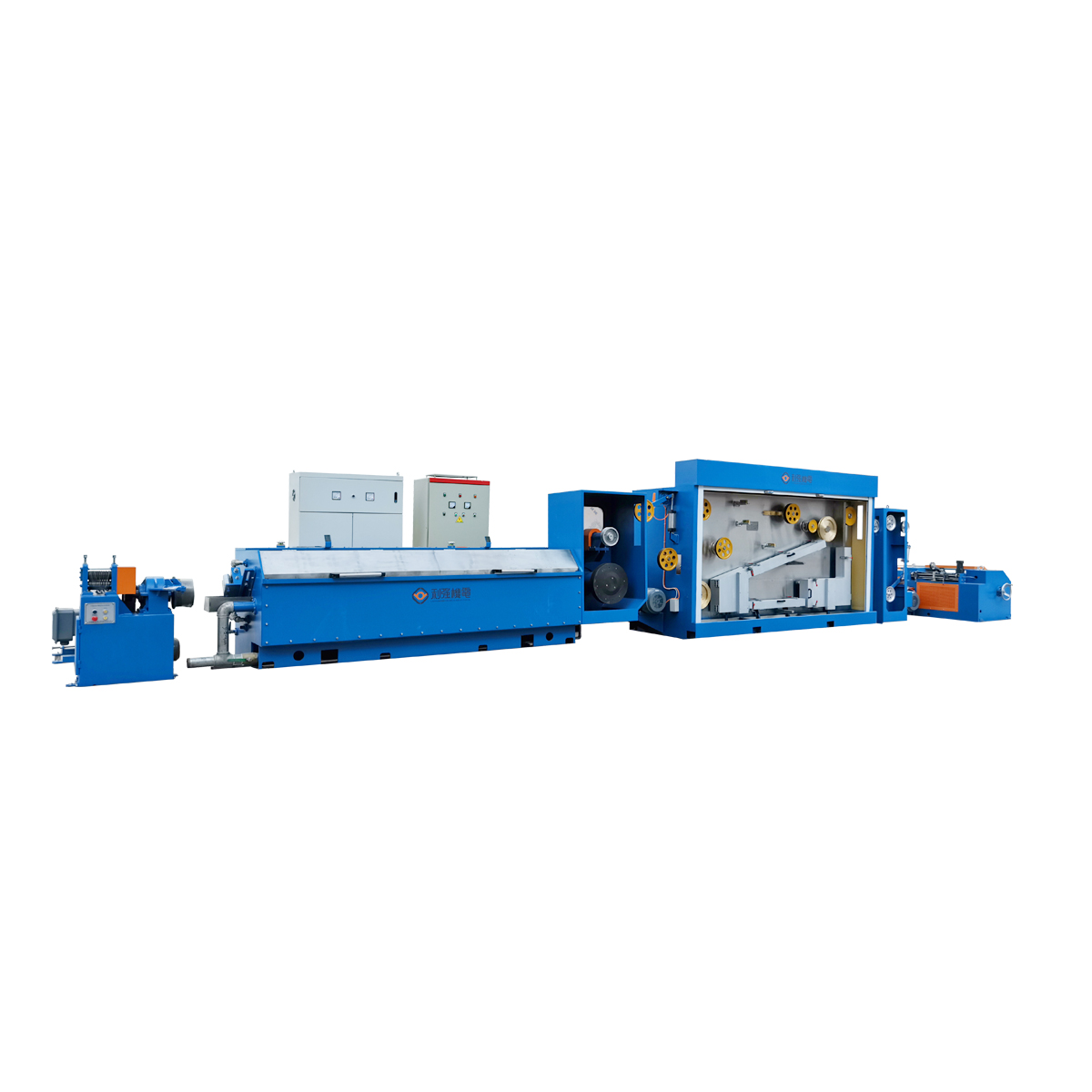
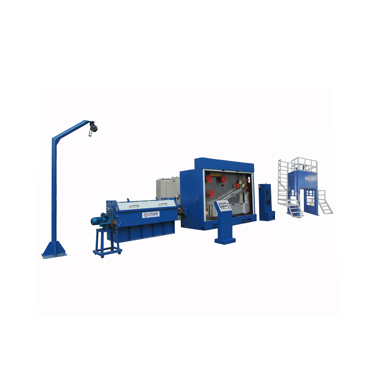
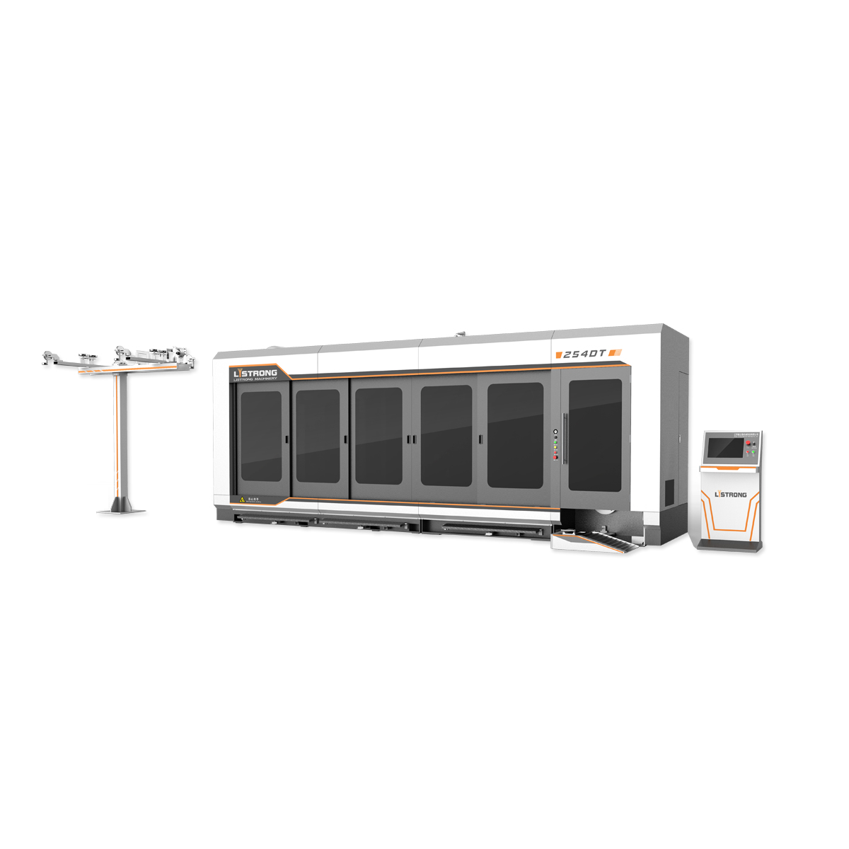
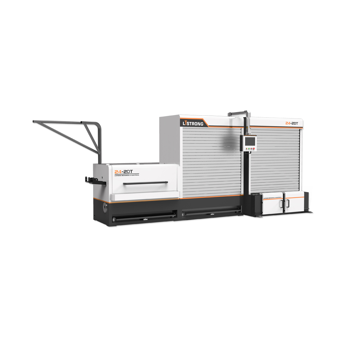
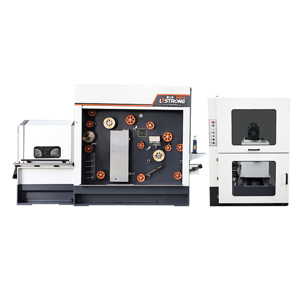
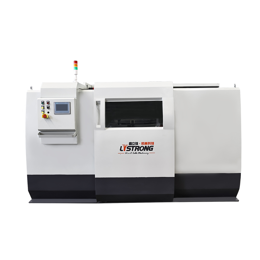
An automatic wire take-up machine collects and evenly winds wire, cable, or filament from a processing line (cutting, stranding, drawing, coating, or extrusion) onto reels, spools or bobbins. These machines maintain consistent tension, measure length/turns, and synchronize with upstream equipment to avoid line stoppages and waste. Typical applications include electrical wire production, cable assembly, wire forming, and PCB coil winding.
Key Components and How They Work
Level-Wind or Layer-Wind Mechanisms
Level-wind systems move the wire carriage back and forth so that wire is laid evenly across the reel width. Layer-wind systems build layers with guides or traverse mechanisms, often with programmable overlap. Choose a mechanism based on spool geometry and required winding quality.
Tension Control and Brake Systems
Precise tension control prevents wire stretch, kinks, and slippage. Common solutions are dancer-arm feedback, load-cell sensing, and electronic closed-loop torque control on the motor or brake. Select tension range and feedback type to match wire diameter, material, and line speed.
Measuring, Counting, and Feedback
Integrated length counters, encoder feedback, or motor-step counting ensure accurate metering. Advanced units offer recipe storage, PLC integration, and incremental stop/start tied to upstream processes. Accuracy spec examples: ±0.5% typical for encoder systems; better than ±0.1% when using high-resolution encoders and compensation algorithms.
How to Select the Right Machine (Practical Checklist)
- Material & diameter range — confirm min/max diameters and if the unit supports multi-core or insulated cable.
- Line speed & throughput — ensure motor and carriage dynamics match the maximum upstream speed (m/min or m/s).
- Tension accuracy — check tension control method (dancer, load cell, or torque control) and specified stability.
- Spool sizes & core adaptors — confirm mechanical adaptability for flange diameter, hub bore, and spool width.
- Controls & connectivity — PLC/Modbus/Profinet options, HMI recipe storage, and I/O for integration.
- Safety features — e-stops, guarded moving parts, and automatic cut-and-stop on wire break detection.
- Maintenance & spare parts availability — motor drives, encoders, belts, and wear parts lead times.
Installation & Integration Best Practices
Mechanical Alignment
Mount the take-up on a rigid base plate aligned with the upstream payout or processing axis. Use laser or precision straightedge to align entry guides and tension sensors so the wire path is planar and free of side loads. Incorrect alignment introduces friction, uneven winding and premature wear.
Electrical & Control Integration
Coordinate encoder signals and motor control with the line PLC. Configure acceleration/deceleration ramps to avoid jerk-induced breaks. Calibrate the encoder counts-per-meter and validate length accuracy with test runs. Enable alarms for encoder loss, tension out-of-range, and overrun conditions.
Start-up Procedure (Step-by-step)
- Inspect guides and spools for burrs; mount spool and secure hubs/adaptors.
- Set initial tension low, run at low speed and watch winding pattern.
- Gradually increase speed to production rate while monitoring dancer/load-cell response.
- Verify length/count accuracy vs. measured sample and adjust encoder scaling if necessary.
Maintenance Schedule & Troubleshooting
Daily Checks
- Inspect guide surfaces, clean debris, and verify tension sensor readings at idle.
- Confirm encoder signal LEDs and HMI status without fault codes.
Weekly & Monthly Tasks
- Lubricate bearings and lead-screws per manufacturer intervals; inspect belts and replace if showing >10% wear.
- Test tension calibration with reference weights; re-tune PID loops if the system is oscillating.
Common Problems and Fixes
- Layering irregularities: Check carriage travel speed vs. spindle speed ratio and verify guide geometry; adjust traverse pitch.
- Wire slip: Inspect clutch/brake surfaces and tension compensation; switch to load-cell feedback if dancer-arm hunting persists.
- Encoder errors: Check cable shielding, connector seating, and grounding. Replace encoder if counts are inconsistent.
Specification Comparison Table (Example)
| Model |
Max Speed (m/min) |
Tension Range (N) |
Drive Type |
Control |
| TW-500 |
400 |
0.5–50 |
Servo + Brake |
PLC + HMI |
| LW-120 |
220 |
1–100 |
Stepper + Brake |
Embedded HMI |
Safety, Compliance & ROI Considerations
Ensure CE/UL certifications where applicable, and implement interlocks and guards on moving parts. Calculate ROI by including reduced scrap, labor savings from automation, increased line uptime, and improved winding quality. Example ROI formula:
- Annual savings = (reduction in scrap kg × material cost) + (operator hours saved × labor rate) + (increase in sellable throughput × margin)
Final Recommendations for Buyers and Engineers
For new installations, prioritize a servo-driven take-up with encoder feedback and load-cell tensioning for best performance across wire types. For retrofit on slower lines, stepper-based systems with mechanical brakes may suffice. Always request factory acceptance tests (FAT) with your actual wire or a representative sample, and ask for detailed maintenance manuals and spare parts lists before purchase.
If you want, I can generate a one-page checklist you can print and take to vendor meetings (spool adaptors, encoder specs, integration I/O mapping and sample FAT test script) — tell me which three vendors/models you’re comparing and I’ll build it.


 中文简体
中文简体 русский
 Español
 عربى
عربى


Contact Us